Menu:
SEL-321 Revitalization Project
Description
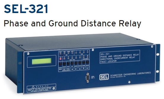
The SEL-321 is a protective relay for high-voltage electric transmission lines. It has been one of SEL’s flagship products for over 20 years. Electric utility companies who have come to depend on its quality and reliability are still ordering new SEL-321s for use in their substations.
In 2012, several key digital hardware components in the SEL-321 were discontinued by their suppliers. I worked on a project to revitalize the SEL-321’s legacy hardware by replacing the obsolete components with contemporary ones. The project also focused on making the product cost less to manufacture. This project extended the SEL-321’s lifetime by seven years, allowing SEL to continue selling it to loyal customers who have come to depend on its reliable performance and long lifetime.
I have lead similar projects to extend the lifetime and/or reduce the BOM cost of SEL’s legacy products without impacting their quality and reliability. These projects provide unique challenges, such as working with old, undocumented designs and finding unique ways to replace core components while minimizing modifications to existing architecture.
Note: The SEL-321’s technical design information is confidential to SEL, so I will only give a high-level overview of what I worked on.
Project Takeaways
This project allowed me to gain technical experience in the following areas:
- ADC and analog front-end circuit design
- RTL component specification and design
- Setup and hold timing analysis for parallel and serial digital interfaces
- Power usage analysis and point-of-load power supply design
- Regulatory testing to IEEE C37.90 and IEC 61000-4 a standards
- Reverse engineering undocumented hardware designs
My Role
The primary obsolete components that were replaced on this project were the ADC, SRAM, EEPROM, and DUART. The old firmware could not be changed due to issues with customer firmware locks, so a CPLD was added to mesh the old firmware interface to the new digital parts.
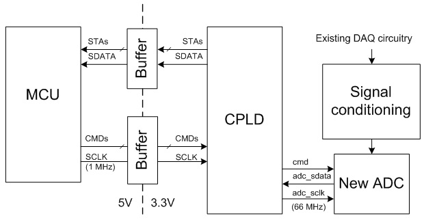
Block diagram of interface between old MCU and new ADC, which uses a CPLD to convert command/status signals and serial data rate
The new ADC had a different analog input range than the old one, so I designed an offset-gain circuit to condition the analog signal from the existing input circuit into the correct range. It also had different command signals and data rate. A CPLD was used to convert the old firmware signals and timing to interface with the new ADC. The existing interface between the MCU and the old ADC was poorly documented, so I analyzed the assembly code to determine timing for the command and data signals, and confirmed the timing using oscilloscope measurements.
I then created an interface specification between the old firmware and the new ADC, detailing the timing requirements for every signal on the interface. This specification drove the RTL design in the CPLD.
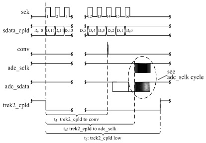
Portion of CPLD timing specification diagram showing relation between signals
The new ADC and CPLD operated at 3.3V logic levels, while the old MCU operated at 5V. Thus, all the signals had to be level-shifted between 3.3V and 5V. I performed a timing analysis to verify setup and hold times would still be met with the delay added by the CPLD and the level-shifting buffers.
The new SRAM and EEPROM components also operated at 3.3V and had different address and data widths than the existing parts. The CPLD was used to decode the existing memory chip enable signals so they would select the appropriate chip and address banks on the new parts.
Many of the new parts were 3.3V parts, because 5V parts are becoming old and uncommon. I designed and implemented the 3.3V point-of-load power supply that powered the 3.3V parts. I performed a power analysis, estimating the total power that would be used by the new 3.3V parts (ADC, SRAM, EEPROM, etc.). I used this analysis to drive component selection and maximum throughput for my design.
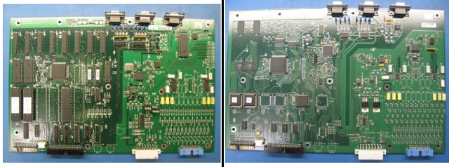
SEL-321 mainboard before (left) and after (right) the revitalization project. The obsolete through-hole components were replaced with modern SMT parts, improving quality and ease of manufacturing
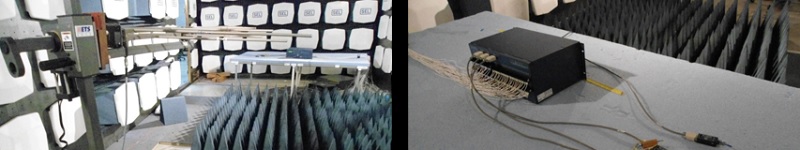
I wrote and performed functional tests for the ADC, CPLD, and 3.3V LDO to verify they operated as required. I also performed system level tests to ensure that the new hardware was compatible with all variants of firmware. I oversaw a full suite of regulatory testing on the product to verify conformance to IEC and IEEE test standards.
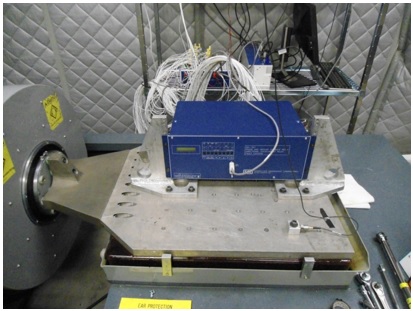
SEL-312 undergoing Vibration testing to IEC 60255-1, -2, -3 test standards
I supported our in-house manufacturing group by helping to troubleshooting inconsistent solder issues that were causing intermittent connections to the fine-pitched leads of the ADC. I provided manufacturing test requirements for the new circuits in the product. I also created a training document for manufacturing technicians that they could use as a reference when troubleshooting manufacturing defects.